In high-precision electronics validation—such as testing 5G millimeter-wave (mmWave) frontends, RFICs, or semiconductor transceivers—engineers frequently encounter a frustrating phenomenon: the voltage measured at the device under test (DUT) is lower than the voltage programmed on the variable DC power supply.
At high currents (e.g., 60 A or more), even a tiny resistance in the test leads can cause a significant voltage drop. This drop can lead to unexpected DUT resets, degraded RF performance metrics (like EVM degradation), or erroneous validation data.
This comprehensive guide explains the science of Remote SENSE (4-wire measurement), contrasts it with standard 2-wire configurations, and provides step-by-step wiring and configuration instructions to ensure absolute voltage accuracy in programmable DC power supplies.
1. 2-Wire vs. 4-Wire (Remote SENSE) Connection
To understand why Remote SENSE is necessary, we must compare it to standard 2-wire sensing.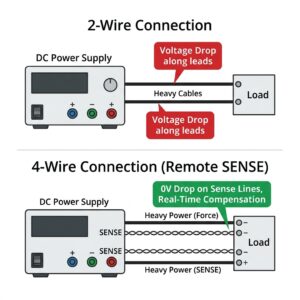
Standard 2-Wire Connection (Local Sensing)
In a 2-wire configuration, the power supply regulates the voltage at its own output terminals. The supply assumes that the voltage at the output terminals is identical to the voltage at the load.[ Power Supply Output (+/-) ] <=====================> [ Load / DUT (+/-) ]
Lead Resistance (R_lead)
4-Wire Connection (Remote SENSE)
A 4-wire connection decouples the power delivery (Force) from the voltage measurement (Sense).- Force lines (Heavy gauge): Carry the main output current to power the DUT.
- Sense lines (Thin gauge, twisted): Connect to a high-impedance feedback circuit inside the power supply. Because the input impedance of the Sense circuit is extremely high (typically megaohms), virtually zero current flows through the Sense wires. Consequently, there is no voltage drop along the Sense lines, allowing the power supply to read the exact voltage at the load terminals and dynamically increase its output to compensate for the drop on the Force lines.
2. Mathematical Case Study: 5G mmWave Power Validation
Let’s look at a real-world scenario often encountered by RF validation engineers testing high-integration active phase-array antenna modules (such as those from Sivers Semiconductors):- DUT Working Voltage: 3.3 V
- Operating Current (I): 60 A (under full-power multi-beam transmit state)
- Lead Wire Gauge: 6 AWG (approx. 1.3 m length round-trip, resistance ≈ 3.4 mΩ)
- Terminal Contact Resistance: ≈ 1.6 mΩ (screws, terminal lugs, and clips)
- Total Loop Resistance (R_lead_total): 5.0 mΩ
The Math:
Using a standard 2-wire connection: V_drop = 60 A × 0.005 Ω = 0.30 V V_load = 3.30 V – 0.30 V = 3.00 V A drop of 0.3 V means the voltage drops by 9%. For a high-performance 3.3 V RFIC, this voltage dip will trigger under-voltage lockout (UVLO), cause the chip to reset, or severely skew critical RF measurements like EVM (Error Vector Magnitude) and phase noise. With Remote SENSE enabled: The power supply detects that the DUT end is only receiving 3.00 V. The internal feedback loop automatically boosts the output voltage at the front/rear panel terminals to 3.60 V. As a result, the DUT receives a rock-solid, regulated 3.30 V at its terminals.3. Step-by-Step Configuration & Wiring (e.g., C-Series Power Supplies)
For high-current industrial DC power supplies like the ETOMMENS C-Series (e.g., eTM-30200C), SENSE is disabled by default to prevent accidental open-loop issues when no sense wires are connected. Follow these steps to configure both hardware and software:

ETOMMENS eTM-30200C Programmable DC Power Supply
High-precision 30V / 200A (6000W) DC power supply equipped with rear-panel Remote SENSE (4-wire compensation) terminals, trusted by global 5G RFIC validation labs.
👉 View eTM-30200C Product DetailsStep 1: Remove the Rear Terminal Shorting Clips
Out of the box, the power supply has metal shorting clips bridging the local output terminals to the SENSE terminals:+(Output) is shorted toS+(Sense +)-(Output) is shorted toS-(Sense -)
Step 2: System Menu Configuration (Software Enable)
- Turn off the main AC power switch on the power supply.
- Press and hold the ON/OFF button (Output control) on the front panel.
- While holding the ON/OFF button, turn on the main power switch. The display will boot into the engineering settings menu.
- Rotate the voltage knob until you see the SENSE option (displayed as
S-EN,S-, orF-depending on the firmware version). - Rotate the current knob to change the value from
OFF` to `ON. - Press the **ON/OFF** button again to save the configuration and exit the menu.
Step 3: Wiring Connection
- Connect the heavy-duty Force cables from the positive
(+)and negative(-)output terminals of the power supply to the positive and negative terminals of the DUT. - Connect thin, twisted-pair Sense wires (22-26 AWG is sufficient) from the
S+andS-terminals directly to the input contacts of the DUT.
4. Troubleshooting & FAQ
Q1: What happens if I reverse the SENSE wire polarity?
If you connectS+ to the negative load terminal and S- to the positive load terminal, the power supply will receive a negative voltage feedback signal. The internal regulation loop will assume the output voltage is too low and will immediately increase the output to its maximum limit, triggering OVP (Overvoltage Protection) or potentially damaging the DUT.
Always double-check SENSE wire polarity before turning the output ON.
Q2: What happens if the SENSE wires get disconnected during operation?
If a SENSE wire breaks or is disconnected while the output is active, the feedback loop goes open-circuit. The power supply will detect 0 V on the sense line and attempt to raise the output voltage to compensate. Modern programmable power supplies have Open Sense Protection that detects this state and shuts down the output within milliseconds to protect the load.Q3: What is the maximum voltage drop the SENSE function can compensate?
Most premium DC power supplies can compensate for a maximum lead voltage drop of 1 V to 3 V total (sum of positive and negative leads). For example, if you set the supply to 10 V and the lead drop is 1.5 V, the terminals will output 11.5 V. If the lead drop exceeds the maximum compensation range, the supply will flag an error or limit the output.Q4: Can I use SENSE with long cables?
Yes. SENSE is designed for long run-lengths (up to several meters). However, long wires can pick up electromagnetic interference (EMI) or ripple from nearby high-frequency sources (like RF transmitters). Always use twisted-pair cabling for the SENSE lines and, if testing in high-noise RF environments, use shielded twisted cables with the shield grounded at the power supply end only.Summary: Checklist for SENSE Implementation
| Step | Action | Notes |
|---|---|---|
| 1 | Remove metal shorting clips from rear panel | Essential for open feedback |
| 2 | Enable S-EN in System Menu | Access via ON/OFF + Power ON |
| 3 | Run heavy Force lines to load | Sized for peak operating current |
| 4 | Run twisted Sense lines directly to load input pads | Decoupled from force wire contacts |
| 5 | Verify polarity (S+ to +, S- to -) | Prevents overvoltage shutdown |