The commercial rollout of 5G millimeter-wave (mmWave) and next-generation satellite communications (SATCOM) has forced RF validation engineers to deal with unprecedented power supply requirements. Unlike traditional cellular architectures, mmWave systems rely on active phase-array antennas (AiP – Antenna in Package) and massive MIMO beamforming RFICs to overcome high atmospheric path loss.
These active antennas require a combination of high power, precision voltage regulation, and extremely fast dynamic response during testing.
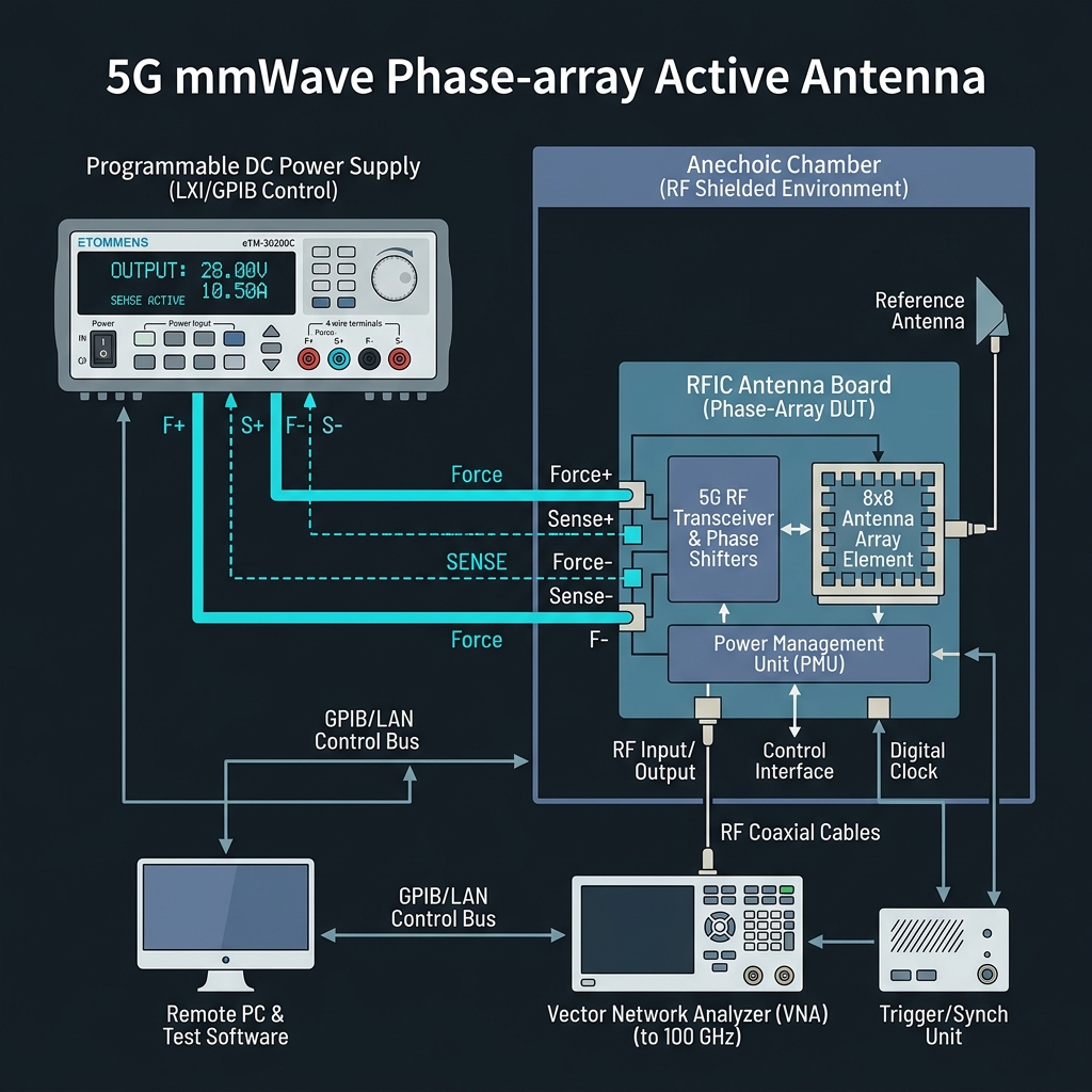
In this application note, we examine the unique electrical challenges encountered on a transceiver test bench setup, why lead wire voltage drops corrupt RF validation measurements like EVM (Error Vector Magnitude), and how to configure a Remote SENSE (4-wire) feedback loop to secure stable test results.
1. The mmWave Power Dilemma: High Current, Low Voltage, Fast Swings
Active phase-array antenna modules integrate RF amplifiers (HPAs, LNAs), phase shifters, and beamforming logic directly onto a single silicon substrate. This density creates three distinct challenges for the laboratory power supply:
- Low Operating Voltage (3.3 V to 5 V): The silicon transceivers run on low-voltage rails, where the margins for noise and voltage deviations are narrow.
- Massive Operating Currents (60 A or more): Under full transmit beamforming operations, active antenna arrays can draw huge continuous currents.
- High Dynamic Swings: Beamforming switching, pulse mode operations, and rapid time-division duplexing (TDD) cycle the current from near-zero to peak values within microseconds.
Under these conditions, standard 2-wire cabling layouts create severe voltage degradation.
2. How Lead Wire Voltage Drops Distort RF Metrics
If you connect a standard variable DC power supply to a mmWave antenna module using a traditional 2-wire local sensing method, current (I) flowing through the wire resistance (R) produces a voltage drop (V_drop = I × R).
At 60 A, a minor loop resistance of 5.0 mΩ (common for cables and connector pins combined) drops 0.30 V before reaching the test board.
For a 3.30 V active array, receiving only 3.00 V leads to immediate performance issues:
- HPA Gain Compression: The power amplifiers (HPAs) lose headroom. The output power drops, causing the amplifier to enter compression earlier than expected.
- EVM (Error Vector Magnitude) Degradation: Voltage drops during transmit bursts cause the RF amplifiers to phase-shift under load, which introduces constellation distortion and worsens EVM.
- System Resets: If the voltage drops below the chip’s internal threshold, the entire beamformer resets, ruining long test automation cycles.
3. Solving the Problem with 4-Wire Remote SENSE
To defeat voltage drops in 5G mmWave testing power supply configurations, validation benches must implement Remote SENSE (4-wire Kelvin sensing).
By separating the current-carrying lines (Force) from the measurement feedback lines (Sense), the power supply reads the exact voltage directly at the antenna PCB board. Because virtually zero current flows through the high-impedance SENSE lines, there is no voltage drop. The power supply automatically raises its terminal output voltage to compensate for the line drop on the Force lines, ensuring a rock-solid 3.30 V at the DUT.
For physical wiring layouts and setup details, please refer to our step-by-step SENSE wiring guide.
4. Hardware Case Study: Sivers Semiconductors mmWave Validation
This scenario isn’t just theoretical. Top-tier semiconductor manufacturers like Sivers Wireless (a leader in mmWave beamforming RFIC technology) utilize the ETOMMENS eTM-30200C (30 V / 200 A) to run their active antenna test benches.
During validation runs of their 5G transceiver chipsets at continuous loads of 60 A inside anechoic chambers, Sivers engineers used the C-Series Remote SENSE feature to maintain exactly 3.3 V at the DUT, completely eliminating transmission errors and EVM degradation.

ETOMMENS eTM-30200C Programmable DC Power Supply
High-precision 30V / 200A (6000W) DC power supply equipped with rear-panel Remote SENSE (4-wire compensation) terminals, trusted by global 5G RFIC validation labs.
👉 View eTM-30200C Product DetailsWhy B2B Labs Choose the eTM-30200C:
- Millisecond Voltage Recovery: The C-Series feedback loop responds dynamically to TDD pulse loading, keeping voltage stable during rapid beamformer state switches.
- Open Sense Fail-Safe: If a SENSE line is damaged inside the anechoic chamber, the supply shuts down power output instantly, preserving high-value prototype RFICs.
- Clean Output: Low ripple and noise specifications prevent the power supply from introducing unwanted phase noise onto the RF transmitter.
Conclusion
Validating active phase-array antennas for 5G mmWave and SATCOM requires power supply solutions that look beyond basic voltage and current ratings. At high operating currents, lead wire voltage drop is a critical source of error.
Implementing a 4-wire Remote SENSE topology using a reliable, high-speed programmable power supply like the ETOMMENS eTM-30200C is mandatory to ensure clean EVM data, stable beamforming validation, and efficient development timelines.