For engineering leaders in the semiconductor, RFIC, and telecommunications space, the final stretch of product development—the hardware validation campaign—is a high-stakes race against the clock. Weeks are spent booking expensive cleanrooms, reserving time in electromagnetic anechoic chambers, and assembling top-tier engineering talent to validate a new chip or transceiver module.
Yet, many test campaigns hit a sudden, invisible brick wall: erratic DUT (Device Under Test) resets, degraded RF performance, and validation data that fails to match software simulations.
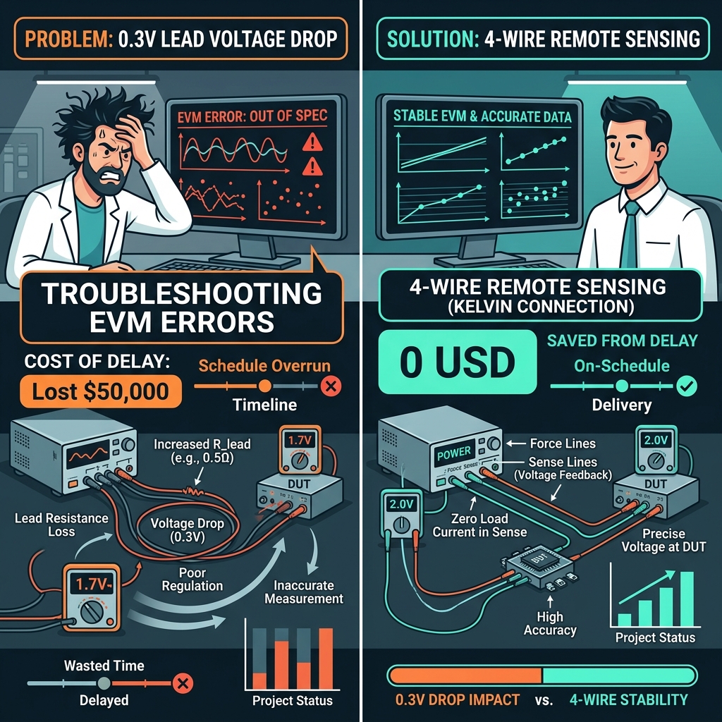
Often, teams spend weeks and tens of thousands of dollars troubleshooting the chip design, assuming a silicon defect. In reality, the culprit is far simpler, yet completely overlooked: a silent 0.3V lead voltage drop between the bench power supply and the test board.
Here is a breakdown of how this electrical phenomenon turns into a B2B project management nightmare, and how industry-leading labs eliminate it with zero added cost.
1. The Physics: How a Micro-Resistance Becomes a Macro-Problem
In low-current electronics testing, the resistance of the cables feeding power to the test board is negligible. But in modern high-performance hardware testing—such as validating active phase-array antenna modules for 5G mmWave or testing high-power computing (HPC) transceivers—operating currents regularly climb to 50A, 60A, or even 100A.
At these high currents, Ohm’s Law (V = I × R) behaves ruthlessly.
Consider a standard testing setup:
- Operating Current (I): 60 A
- Wire Resistance: 3.4 mΩ (standard 6 AWG copper cable, 1.3 m round-trip)
- Contact Resistance: 1.6 mΩ (terminal lugs, banana jacks, and binding posts)
- Total Loop Resistance (R_lead): 5.0 mΩ
Using a standard 2-wire setup, the power supply regulates the voltage at its own output terminals. However, the voltage drop across the cables is:
V_drop = 60 A × 0.005 Ω = 0.30 V
If your 3.3 V RFIC transceiver requires a stable 3.30 V input, it is actually receiving only 3.00 V at the board terminals. That represents a 9% voltage dip—more than enough to trigger the chip’s Under-Voltage Lockout (UVLO), cause spontaneous microprocessor resets, or degrade signal EVM (Error Vector Magnitude).
2. The Real B2B Cost of 0.3V: Time, Budget, and Delay
While 0.3 V seems minor on paper, the commercial consequences for an engineering project are massive:
💸 Wasted R&D Engineering Hours
When validation data looks degraded (e.g., poor phase noise or high EVM), the immediate reaction is to look for silicon or layout design flaws. Typically, three to four senior RF and analog engineers are pulled in to troubleshoot.
- Average Cost: 2 to 3 weeks of troubleshooting by a team of 4 senior engineers can easily waste $15,000 to $25,000 in billable engineering hours, searching for a bug that doesn’t exist in the silicon.
💸 Expired Lab & Chamber Bookings
High-performance RF validation requires specialized test chambers (e.g., OTA chamber runs) which can cost thousands of dollars per day to rent. If your hardware is unstable due to voltage drops during these slots, the booking fee is completely lost.
💸 Time-to-Market Delays
A two-week delay in validating a new chipset can postpone product launch, leading to missed client design-in cycles and potentially costing hundreds of thousands of dollars in lost market opportunity.
3. The Solution: Transitioning to a Remote SENSE (4-Wire) Protocol
To bypass cable resistance entirely, modern laboratories must upgrade their testing setups from a standard 2-wire configuration to 4-Wire Kelvin Sensing (commonly referred to as Remote SENSE).
In a Remote SENSE configuration, the power supply splits its duties:
- Force Lines (Power): High-gauge cables carry the heavy current (60 A) to the DUT.
- Sense Lines (Feedback): A pair of thin, twisted wires connect directly to the power input pads of the DUT. Because the input impedance of the power supply’s SENSE circuit is in the megaohms, practically zero current flows through the Sense wires.
Because no current flows in the Sense lines, there is zero voltage drop along them. The variable DC power supply reads the exact, real-time voltage at the DUT terminals and dynamically boosts its output (e.g., outputting 3.60 V at the chassis to deliver exactly 3.30 V at the board).
For a complete step-by-step guide on how to wire these feedback loops, you can refer to our step-by-step SENSE wiring guide.
4. Hardware Spotlight: The ETOMMENS eTM-30200C
Choosing a programmable DC power supply with reliable Remote SENSE is the foundation of any high-current hardware validation bench.
The ETOMMENS eTM-30200C is an industrial-grade 30 V / 200 A (6000 W) programmable power supply designed specifically for high-current validation challenges.

ETOMMENS eTM-30200C Programmable DC Power Supply
High-precision 30V / 200A (6000W) DC power supply equipped with rear-panel Remote SENSE (4-wire compensation) terminals, trusted by global 5G RFIC validation labs.
👉 View eTM-30200C Product DetailsWhy B2B Labs Choose the eTM-30200C:
- Active Remote Sense Compensation: Automatically compensates for up to 1.5 V of loop voltage drop, guaranteeing sub-millivolt accuracy at the DUT input.
- Fast Transient Response: Prevents voltage undershoots and overshoots during rapid transmit power swings of high-power RF transceivers.
- Proven B2B Credibility: The C-Series platform is actively trusted by leading European semiconductor developers, such as Sivers Wireless, to validate their phase-array 5G transceivers at continuous currents up to 60 A.
5. Action Plan for Lab Managers: Bulletproofing Your Test Campaign
To ensure your next validation campaign finishes on time and under budget, enforce this three-step protocol across your engineering team:
- Enforce 4-Wire Wiring Standards: Ban 2-wire setups for any test drawing more than 10 A. Ensure SENSE lines are soldered directly to the test board’s power plane, not clipped onto power supply leads or alligator clamps.
- Audit Settings on Startup: Verify that the Remote SENSE setting is active in the power supply’s system menu, and that the rear-panel metal shorting clips have been removed.
- Use Shielded Twisted Pairs: For SENSE lines operating near RF power amplifiers, use shielded twisted pair cabling to prevent high-frequency electromagnetic noise from corrupting the power supply’s feedback loop.
By investing fifteen minutes in setting up a proper Remote SENSE connection, B2B engineering labs can safeguard their R&D budget, protect their schedules, and ensure that validation data is 100% accurate.