Motor controller development
Bring up the controller, vary the DC input and observe start-up, speed changes and protective shutdowns. Adjustable voltage and current limits support a controlled first power-on.

Motor & Drive Testing
From the first start-up to repeated load cycles, give your motor controller an adjustable DC source matched to the test.
Compare voltage range, starting current, continuous power and control options for development benches and production fixtures.
Compare Power Supplies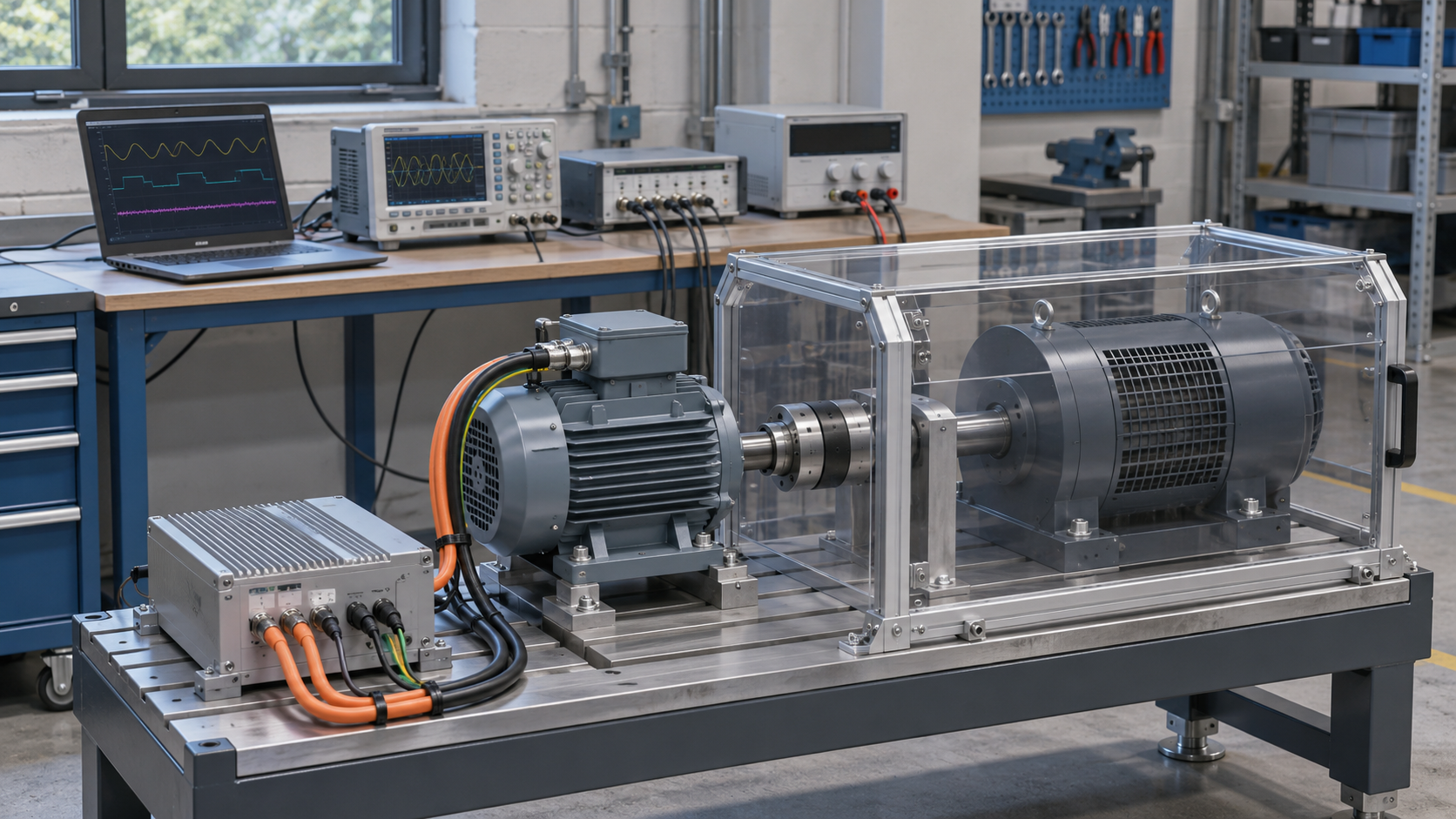
Illustrative motor test environment.
Bring up the controller, vary the DC input and observe start-up, speed changes and protective shutdowns. Adjustable voltage and current limits support a controlled first power-on.
Run the motor against a mechanical load and track input current, speed and temperature over repeated cycles. Continuous power, cooling and the acceleration profile shape the supply requirement.
Repeat forward/reverse operation, pulse counts and frequency settings across test stations. Choose the number of channels and the control method that fit the fixture.
The DC supply feeds the motor controller. The controller drives the motor, while the load and measurement system reveal how it performs.
Control and measurement: PC or PLC, voltage/current measurement, speed or torque sensors and temperature acquisition connect according to the test plan. The DC supply provides electrical power; torque measurement and mechanical loading use separate equipment.
Braking and deceleration: a motor drive can return energy to its DC bus. Include a compatible braking or energy-absorption path where required; use a compatible energy-absorption device rather than feeding braking energy back into a source-only bench supply.
Normal running voltage, maximum test voltage and controller input limits. For a 48V controller, choose a range covering the complete input test window, including any planned tests above nominal voltage.
Start-up current, peak duration and load changes. If the supply reaches its current limit, its output voltage can fall and interrupt the controller. Allow capacity for the planned start-up profile.
Running current, electrical input power, test duration and cooling. A 48V input drawing 40A requires 1,920W at that operating point, before allowance for the rest of the test profile.
Deceleration rate, load inertia and energy returned to the DC bus. Select the drive’s braking arrangement or a suitable bidirectional test system for tests that return power.
Manual adjustment or automated setpoints; RS232, RS485 or USB configuration; sample rate and logging requirements. Capture fast electrical transients with appropriate measurement equipment.
Independent axes, total simultaneous demand, cable voltage drop and terminal ratings. Coordinate output limits, fusing, emergency stop and guarding with the complete test fixture.
Choose the DC range and current capacity for your controller, then open a model to select its available input, connection and control options.
Lower-voltage motor controllers and fixtures with substantial running or acceleration current.
Compare Recommended ModelsController input tests that need a wider DC range than a 60V source can provide.
View Recommended ModelDedicated pulse, direction and multi-channel stepper test requirements.
Compare Stepper Models24V and 48V controller benches within a 0–60V test window. Adjustable 0–60V output and 0–50A current control suit DC source requirements within this range. CV/CC operation, preset settings and an independent output switch support bench setup; optional communication interfaces support PC-controlled setpoints.
View Product & OptionsLower-voltage, higher-current fixtures. The 0–30V range and 0–200A current control make this a candidate for 12V or 24V controller tests with high input-current requirements. Size the connections and input configuration for the operating point and acceleration profile.
View Product & OptionsController tests above a 60V supply range. Adjustable 0–120V output and 0–30A current control accommodate a wider DC input sweep. Low ripple and noise, CV/CC operation and optional remote interfaces support development and repeatable source settings.
View Product & OptionsA wider voltage range does not replace the current needed during acceleration. Compare the full input test window, sustained current and peak duration before choosing between the 60V and 120V models.
For braking tests, include the required energy-absorption hardware in the bench design.
C-series bench features: low-ripple, low-noise output; voltage/current presets; four-digit LED display; encoder adjustment; CV/CC operation; output on/off control; temperature-controlled cooling; overvoltage, overcurrent, overpower, overtemperature and short-circuit protection. RS232/RS485/USB, SENSE compensation and external trigger are configuration-dependent options. AC input selection can limit available output power; review the selected product options before ordering.
For pulse and direction tests, compare dedicated stepper equipment alongside the test fixture’s wiring and total current demand.
Four-channel production and driver evaluation fixtures. 60V / 5A total rating, adjustable 30Hz–9999Hz frequency, 0–65,000 pulse count and CW/CCW operation. Total channel current must remain within the unit rating.
View Specifications & ConfigurationHigher channel-count stepper fixtures. Compare the eight-channel arrangement when the test calls for more connected channels. Review shared output limits and the required pulse, direction and control configuration on the product page.
View Specifications & ConfigurationBipolar stepper test requirements. Review the 60V / 5A model for the required motor wiring, operating frequency and test sequence. Match the equipment configuration to the motor and driver arrangement.
View Specifications & ConfigurationView More Stepper Motor Driver Power Supplies
C-series models offer product options and online ordering. Stepper models currently use the configuration and quotation options shown on their product pages.
For testing an existing motor controller, use a DC supply matched to its input range and acceleration demand. A dedicated stepper test source serves a different setup, with motor-drive and pulse functions selected for the motor and fixture. Compare the required channel count and drive functions before choosing between these types.
Front-panel controls suit manual voltage sweeps and development checks. Repeated test sequences need an available interface and compatible commands for the station controller. Coordinate source settings with speed, torque and electrical measurements from the test equipment.
Match the AC input option, output leads and terminal ratings to sustained current and starting demand. Consider voltage sensing where supported for longer connections. For deceleration tests, provide a suitable braking-energy path rather than relying on a conventional DC source to absorb returned energy.
Choose from the controller’s complete input range and current profile. The eTM-6050C provides 0–60V and 0–50A control for tests within that window. If the test voltage exceeds 60V, consider a wider-range model such as the eTM-12030C, provided its current and power capability also cover the test.
It depends on the motor, controller current limits, acceleration settings and mechanical load. Use the measured or specified start-up current and its duration, as well as the continuous input current. The supply must support the intended profile without an unwanted voltage drop or protective shutdown.
Do not use them as regenerative sinks. When the drive returns energy to the DC bus, use a compatible braking arrangement or a bidirectional supply/load system rated for that energy flow.
A brushless motor normally needs its matching electronic controller to commutate the motor. Connect the DC source to the controller’s input within its ratings. Motor phase wiring and control signals follow the controller and motor documentation.
Multiple channels help test several drivers or axes. Check whether the test requires independently adjustable DC outputs, dedicated pulse/direction functions or both, and account for the total simultaneous current demand.
Manual control suits setup and individual checks. Automated voltage settings are useful for repeated test cycles and controller input sweeps. Select the required interface on the product page and match its command support to your test software.
Yes. Open a C-series model, select its available input and control options, and add it to your cart. Dedicated stepper configurations use the purchase or quotation options displayed on their individual product pages.
ETOMMENS serves small and medium-sized businesses, large enterprises and multinational groups, including customers in North America, Europe and the Middle East. Adjustable bench supplies and dedicated stepper equipment offer different paths for motor development and production testing.
Explore the full variable DC power supply range, or compare the motor-test models above.
You can buy ETOMMENS DC power supplies for motor testing online at VariableDCPowerSupply.com. In-stock models dispatch within 1–3 business days after payment, with approximately 10 business days in transit. Free worldwide DDP shipping includes customs clearance, import duties and taxes.
Lead times for custom configurations are confirmed with the quotation.